What Is a Linear Guide Rail?
A linear rail, also called a slide rail or linear motion guide, is commonly used in applications requiring precise and high-speed linear back-and-forth movement. It can handle torque to a certain extent. A linear rail enables accurate linear motion with exceptional precision in high-load scenarios. It is utilized in various industries, including machine tools, electronics, medical devices, and robotics. One of its key benefits is its capability to deliver reliable motion within a limited space.
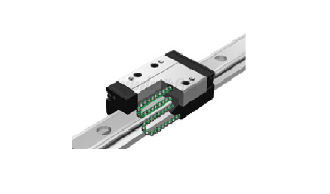
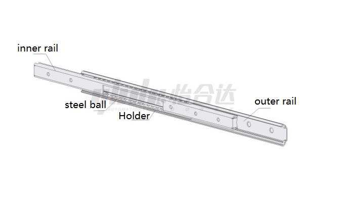
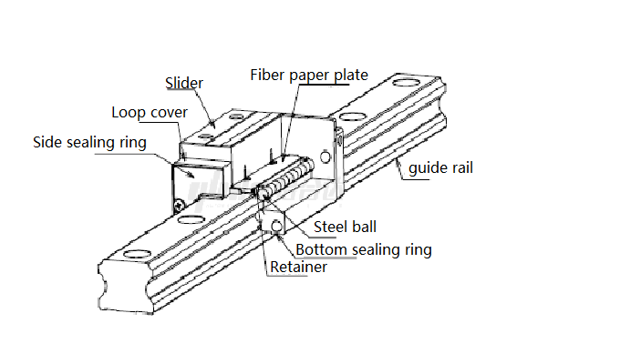
Components of a Linear Rail
A linear guide rail is mainly composed of a rail and a carriage. The carriage has four rows of steel balls (two rows for miniature rails) that facilitate smooth motion by rolling along the rail.
Types of Linear Guide Rail
(1) Circular Guide
By the linear bearing and linear shaft with the use, from the appearance of the cylindrical, can be assembled with a circular hole. At the same time, linear bearings can also be used with the slider to achieve flat installation. The installation and use of circular guide are more convenient, saving space. As shown:
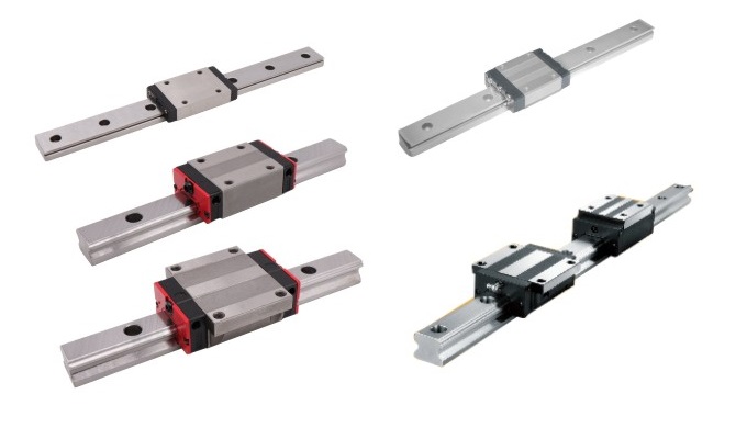
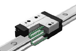
(2) Square Guide
By the square slider and square guide with the use of square, from the appearance of square. From the friction, can withstand the load consideration, square guide is the guide and slider surface contact friction, friction is larger, uniform load, need frequent oil lubrication. As Figure:
Linear Guide Rail Applications
Linear rails are well-suited for various applications requiring reciprocating motion and find widespread usage across multiple industries. They excel in achieving high precision or high-speed linear motion. Specifically, linear rails are commonly employed in machine tools, electronics, medical equipment, and robotics. In the machine tool industry, linear rails enable heavy-duty handling, precise positioning, and machining operations. In the electronics industry, they are utilized in automated assembly lines and motion components of electronic devices. In the medical field, linear rails are applied for precise guidance in surgical robots and medical equipment. In the robotics industry, linear rails are employed for robot motion and positioning control. The versatility and exceptional precision of linear rails make them critical for meeting diverse application requirements.
Product Features
Linear guide rails possess the following key features:
- The automatic self-alignment function enables automatic adjustment of the gap between the rail and the carriage, ensuring smooth motion.
- High load capacity allows for handling heavier loads.
- Long service life, durable, and maintains high performance over extended usage periods.
- High precision capabilities enable precise linear motion.
How to Choose the Linear Rails
When select the linear guide rails, the following principles are typically considered:
- Determine the operating conditions, including factors such as environmental temperature and humidity.
- Choose a suitable model based on the operating conditions.
- Perform load calculations to determine the actual load the rail needs to bear.
- Conduct equivalent load calculations, taking into account dynamic loads during motion.
- Verify the static safety factor to ensure the rail can handle the expected load and provide adequate safety.
- Calculate the average load, considering the rail's average load throughout its service life.
- Perform service life calculations to ensure the rail meets the required lifespan.
- Confirm the rail's rigidity characteristics based on stiffness requirements.
- Specify the desired precision level and select the appropriate rail precision grade.
- Choose appropriate lubrication and dust protection measures to ensure optimal rail performance.
How to Properly Adjust a Linear Guide Rail?
Here are the specific steps for adjusting a linear rail:
1) Secure a reference steel wire with a tolerance of 1/2000mm on both sides of the rail. Use adjustment screws to fine-tune the positions of the shims on each side, maintaining a consistent distance from the reference wire. This distance will serve as the benchmark spacing.
2) Apply a tensile force of 20N between the main rail and the sub-rail. Use a precision steel tape with an accuracy of 1/2000mm to measure the distance between the rails in the middle, ensuring it matches the span of the CNC lathe. If it doesn't align, make comprehensive adjustments using an overall steel wire, ensuring the benchmark spacing remains unchanged.
3) Measure the flatness on both sides of the main rail and the sub-rail using a precision level with an accuracy of 1/10000mm. Adjust the rail's adjustment bolts to maintain the flatness within a range of 0.5mm.
4) Secure the edges of the main rail and the sub-rail with dowel pins, creating benchmarks for adjusting the rail's lateral and vertical level, flatness between the main rail and the sub-rail, and spacing between them. The rail's parallelism should be based on the benchmark spacing between the steel wire and the side edge.
5) Adjust the spacing between each face of the main rail and the sub-rail
Installation and Removal
Installation:
1) Use an emery cloth to clean the installation surface, removing rough edges and debris.
2) Place the rail flat on the reference surface, ensuring the rail's reference side faces the lateral mounting surface.
3) Use screws to secure the rail onto the reference surface, being careful not to fully tighten them and ensuring they align with the rail's mounting holes.
4) Adjust the straightness of the rail and progressively tighten the track positioning screws one by one.
5) A torque wrench tightens the rail assembly screws according to the specified torque values.
6) For paired rails, follow steps 1 to 5 for their installation.
Disassembly:
1) Reverse the installation steps, using a torque wrench to gradually loosen each rail assembly screw.
2) Loosen the track positioning screws.
3) Gradually loosen the screws that secure the rail, but do not completely remove them.
4) Remove the rail from the reference surface.
5) If needed, continue disassembling the paired rails, following the steps above.
By following these steps for installation and removal, you can ensure the proper installation and reliable disassembly of the linear rail. Handle the rail carefully during the process to prevent any damage to its structure and functionality.
Maintenance and Care
The steps for maintaining and caring for a linear slider rail are as follows:
1) Use a clean cloth to thoroughly wipe the three surfaces of the rail and carriage (both side surfaces and the top surface), removing dirt and debris.
2) Apply grease evenly to the three surfaces of the rail and carriage (both side surfaces and the top surface), ensuring full coverage of the entire surface.
By following these steps for maintenance and care, you can ensure the proper functioning and extended lifespan of the linear rail. Please use suitable cleaning agents and lubricants, and perform regular maintenance and care as required.
Common Issues and Analysis:
- Rust:
Cause Analysis: The linear rail does not have rust-resistant properties, and Rust can occur when the oil film on the rail surface is damaged.
- Unusual Noise due to Rust:
Cause Analysis: During the movement of the linear rail, if foreign objects enter or there is poor friction between the carriage and the rail, abnormal Noise may occur. Also, loose rail, wear, or insufficient lubrication can contribute to Noise.
- Uneven Motion:
Cause Analysis: Uneven installation of the rail, uneven carriage wear, oil contamination, or excessive wear can result in uneven motion of the linear rail. Furthermore, external environmental pollution, poor working conditions, or excessive loads can also affect smooth motion.
- Increased Sliding Resistance:
Cause Analysis: Aging, contamination, or insufficient grease in the carriage can lead to increased sliding resistance. Foreign objects, wear, or increased roughness on the rail surface can also contribute to increased resistance.
- Rail Wear:
Cause Analysis: Prolonged use and high-load conditions can cause wear on the linear rail. Wear may be caused by incorrect installation, improper maintenance, impacts or vibrations during use, and friction.
- Rail Deviation:
Cause Analysis: Unstable rail installation, exceeding the rated load capacity, loose bolts, or external impacts can cause rail deviation. Additionally, long-term use and wear can also lead to rail deviation.
For the above issues, timely maintenance, proper installation and usage methods, and regular inspections can help reduce these problems and ensure the smooth operation and longevity of the linear rail.
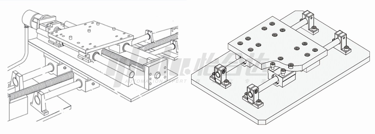
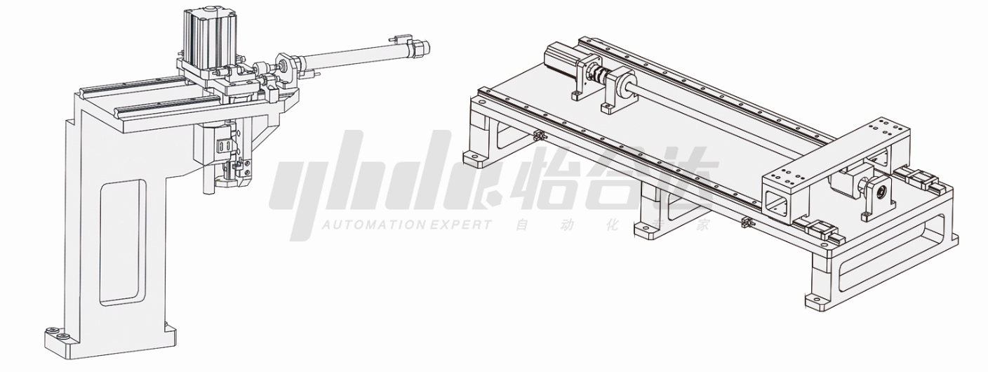
Example Case
Equipment Name: Mask Machine Feeding Mechanism and Mask Machine Ear Strap Welding Mechanism
Design Objective: Enable reciprocating linear motion of workpieces in the mask machine.
Part Application Description: Used with the lead screw, primarily for load-bearing purposes.
In the mask machine's feeding mechanism and ear strap welding mechanism, linear motors and linear modules are utilized to achieve precise reciprocating linear motion of the workpieces. These parts work in conjunction with the lead screw to bear the load of the workpieces. The linear motor converts electrical energy into mechanical motion, driving the linear module to accurately move the workpiece back and forth in a linear direction. The smooth operation of the feeding and ear strap welding processes in the mask machine's manufacturing process is ensured through precise control and coordination.
The precise coordination between the linear module and the lead screw is of utmost importance as they jointly bear the load of the workpieces, ensuring smooth motion and achieving the desired precision. Acting as a transmission device, the lead screw converts rotational motion into linear motion by interacting with the linear module, thereby driving the workpiece along a predetermined path. The precision and reliability of this coordination significantly influence the mask machine's production efficiency and quality.
By appropriately designing and applying these components, the mask machine can achieve efficient workpiece feeding and ear strap welding, thereby enhancing the automation level and production efficiency of the mask production line while ensuring consistent and high-quality masks. This provides reliable technical support for process improvement in mask production and guarantees a dependable supply of masks.
Conclusion
As an essential component for achieving high-precision linear motion, linear guides play a crucial role in the industrial field. By understanding the definition, composition, applications, product features, selection principles, installation, maintenance, and solutions to common issues of linear guides, you can better understand how to choose, install, and maintain them to meet your needs.
Whether in machine tools, electronics, medical devices, or robotics, linear guides play a key role in enabling high-load and high-precision linear motion. Through proper selection and appropriate usage, linear guides can provide stable motion performance, long lifespan, and precise position control, bringing higher efficiency and quality to your applications.
Whether you are a beginner new to linear guides or an experienced professional, we hope the knowledge provided above can help you better understand the principles and applications of linear guides and provide useful guidance and advice for your work and projects. If you need more detailed information or have further questions, please feel free to seek professional consultation and support. May the linear guides perform optimally in your applications and contribute to the success of your projects!
Linear guides play a pivotal role in various industries as vital components for achieving high-precision linear motion. By understanding the definition, composition, applications, product features, selection principles, and installation, maintenance, and troubleshooting methods of linear guides, you can better understand how to select, install, and maintain them to meet your specific needs.
Whether in machine tools, electronics, medical devices, or robotics, linear guides are crucial in enabling high-load and high-precision linear motion. Through proper selection and correct usage, linear guides offer stable motion performance, extended lifespan, and precise position control, enhancing your applications' efficiency and quality.
Whether you're a novice exploring linear guides for the first time or an experienced professional, we aim to provide knowledge that helps you comprehend the principles and applications of linear guides, offering valuable guidance and recommendations for your work and projects. Should you require more detailed information or have further inquiries, please don't hesitate to contact us and we will give you the professional advice and support. May the performance of linear guides in your applications be optimal, driving the success of your projects!