Ⅰ. Aluminum Profile Design
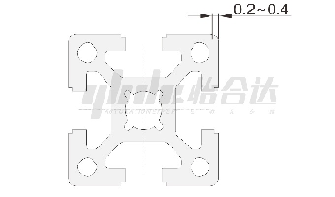
In order to prevent the joints from loosening, the T-shaped grooves of the profiles are all concave. When the aluminum profiles with this structure are butted, only the edges are in line contact. The force deformation of the T-shaped grooves is also limited to the elastic range, which significantly improves the structural strength. stability.
Ⅱ. Aluminum Profile Straightness
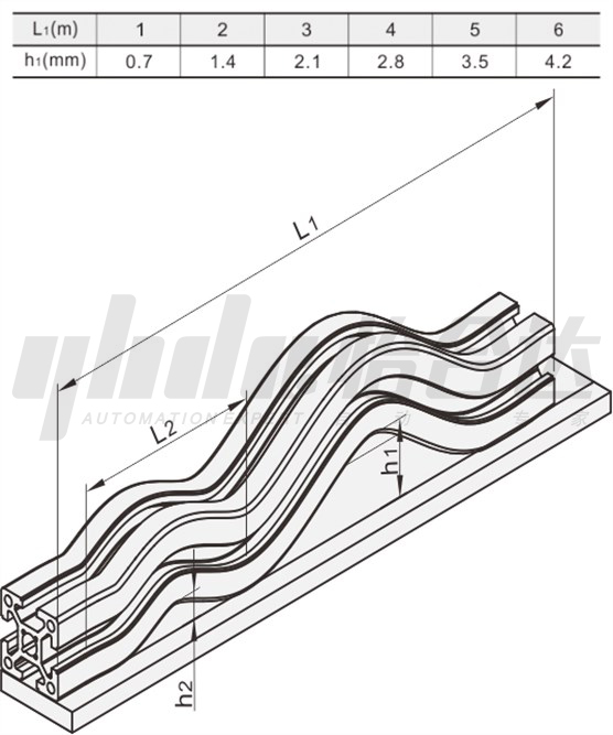
The profile is placed horizontally, the length at any position is L2=300mm, and the maximum bending deformation height h2 does not exceed 0.3mm (L2=300mm, h2≤0.3mm). The bending deformation height h1 of the profile’s full length L1 refers to the following table:
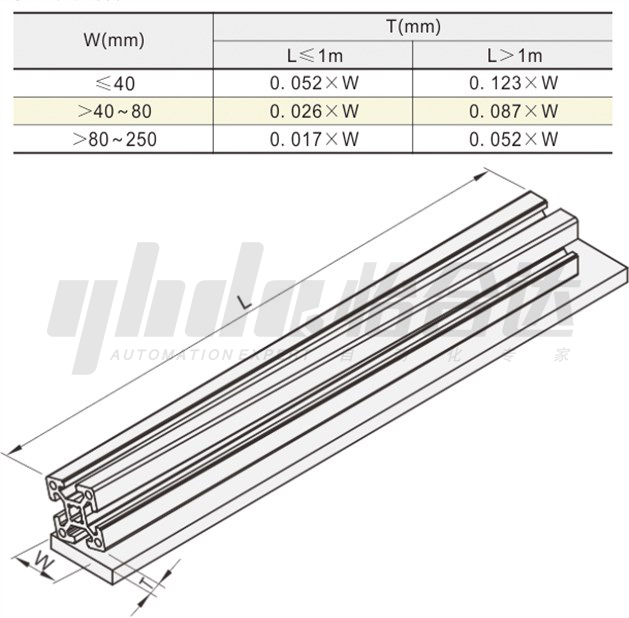
Ⅲ. Aluminum Profile Distortion
The profile is placed horizontally with width W. The ends are raised due to bending and twisting. The distortion height T is calculated according to the following table:
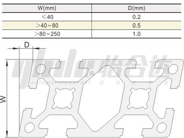
Ⅳ. Aluminum Profile Flatness
The profile is placed horizontally, and the maximum plane tolerance D of the short side W of the profile is shown in the following table:
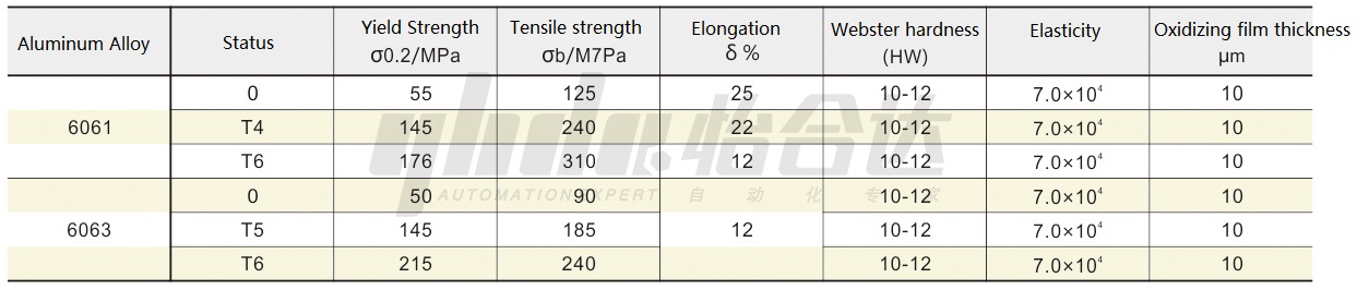
Ⅴ. Aluminum Alloy Mechanical Performance Parameter Table
Ⅵ. Strength Check of Aluminum Profiles
For beams made of ductile materials, when the maximum normal stress on the dangerous section of the beam reaches the yield stress (σs) of the material, the beam is considered to have failed; for beams made of brittle materials, when the maximum normal stress on the dangerous section of the beam reaches When the normal stress reaches the strength limit (σb) of the material, the beam is considered to have failed. That is:
σmax=σs (ductile material) σmax=σb (brittle material)
This is the criterion for judging whether the beam has failed. Aluminum profiles are ductile materials.
In order to ensure that the profile has a sufficient safety margin, the maximum normal stress on the dangerous section of the profile must be less than the allowable stress. The allowable stress is equal to σs or σb divided by a safety factor ns greater than 1 (generally ns is 1.3~1.5) . So, there are:
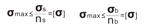
The above two formulas are the calculation criteria for the bending strength of profiles based on the maximum normal stress, also known as the bending strength conditions. In the formula [σ] is the bending allowable stress; ns and nb are the safety factors corresponding to the yield strength and strength limit respectively.
Steps for calculating the bending strength of the profile:
(1) According to the constraint properties of the profile, find the maximum bending moment calculation formula of the profile from Table 1, and calculate the maximum bending moment value.
(2) From the maximum bending moment value, calculate the profile according to the formula The maximum internal stress at the maximum bending moment section.
(3) Look up Table 2 to get the yield strength of the profile used σ0.2. Divide it by the safety factor 1.5 to get the allowable stress [σ].
(4) Use The calculated maximum internal stress is compared with the allowable stress. When the maximum internal stress is less than the allowable stress [σ], the strength of the profile meets the load-bearing requirements. For profiles that produce bending deformation, while meeting the strength conditions, the bending displacement needs to be limited to ensure normal operation, that is, the stiffness conditions should also be met: ![]()
In the formula, L is the span length, ![]() and is the ratio of the allowable deflection to the span length (referred to as the allowable deflection span ratio). In general engineering, only the deflection span ratio of the beam is usually limited.
and is the ratio of the allowable deflection to the span length (referred to as the allowable deflection span ratio). In general engineering, only the deflection span ratio of the beam is usually limited. ![]()
Ⅶ. Examples
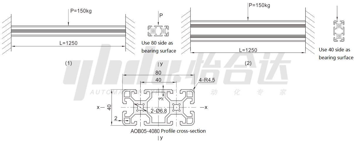
A profile of AOB05-4080 has a length of L=1250 and is fixed at both ends. A load of 150 kg is applied to its middle part to test its strength. As shown below:
Ⅷ. Checking Steps
Step One: Check the flexural strength of the profile.
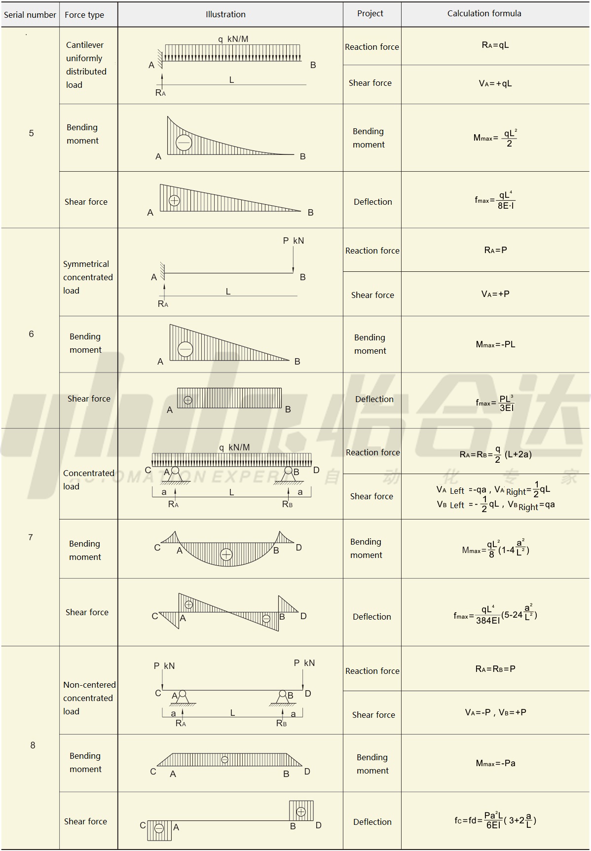
In Table 1, the profile concentrated load simply supported beam structure can be found. The maximum bending moment is Mmax=( ![]() )=150*9.8*1.25/4=459.4/N·m. Check the elastic modulus of AOB05-4080 profile E=70000N/mm2
)=150*9.8*1.25/4=459.4/N·m. Check the elastic modulus of AOB05-4080 profile E=70000N/mm2
Check the profile technical parameter table to get the cross-sectional moment of inertia Ix= 174455mm4 Iy=655220mm4 The bending section coefficient is Wxmax=8722.75mm3Wymax=16380.5mm3.
Substitute into the normal stress formula:
(1. Use surface 80 as the bearing surface): ![]()
(2. Use surface 40 as the bearing surface): ![]()
Looking up Table 2, the yield strength of 6063-T5 is 145 MPa, divided by the safety factor 1.5, 52.67MPa≤ 145/1.5=96.7 MPa, so this profile can meet the strength of 150 kg with 80 faces as the bearing surface. In the same way, 28.05MPa≤145/1.5=96.7 MPa, this profile uses 40 sides as the load-bearing surface to meet the strength of 150 kg.
Step 2: Check the stiffness of the aluminum profile.
According to the maximum deflection formula:
(1: Use surface 40 as the bearing surface):
![]()
According to the formula:
![]()
1.30/1250=0.001=1/1000=0.001, so the stiffness requirement can be met by using the 40-face load bearing profile.
(2: Use surface 80 as the bearing surface):
![]()
According to the formula:
![]()
4.89/1250=0.0039≥1/1000=0.001, so the 80-face load-bearing profile cannot meet the stiffness requirements.
Conclusion: An AOB05-4080 profile with a length of 1250mm needs to carry a load of 150kg. It can only be carried by 40 sides to meet the strength and stiffness requirements.
Ⅸ. List of Commonly Used Aluminum Alloy Beam Reaction force, Shear force, Bending Moment and Deflection Calculation Formulas
Excerpted from Mechanical Design Handbook