100 questions and answers about tolerances and fits, it will definitely come in handy when doing machinery, mold design and processing! What is the limit size? What is the basic deviation? What is fit tolerance? In what situations are different tolerance levels used? If you have a friend who makes machinery or molds, share this article for them.
1. What is a tolerance?
Answer: The amount of variation allowed in part dimensions and geometric parameters is called tolerance.
2. What is called size?
Answer: A number that represents a length value in specific units.
3. What are basic dimensions?
Answer: Make the design the given size.
4. What is actual size?
Answer: It is the size obtained by measurement.
5. What is the ultimate size?
Answer: It refers to the two limit values of allowable dimensional changes.
6. What are the maximum entity state (MMC for short) and the maximum entity size?
Answer: The maximum physical state refers to the state when the hole or shaft has the largest amount of material within the dimensional tolerance range. The size in this state is called the maximum physical size, which is the collective name for the minimum limit size of the hole and the maximum limit size of the shaft.
7. What are the minimum solid state (LMC for short) and the minimum solid size?
Answer: The minimum physical state refers to the state when the hole or shaft is within the dimensional tolerance range and has the least material. The size in this state is called the minimum physical size, which is the collective name for the maximum limit size of the hole and the minimum limit size of the shaft.
8. What is the action size?
Answer: Over the entire length of the mating surface, the maximum ideal shaft size inscribed with the actual hole is called the effective size of the hole. The size of the smallest ideal hole external to the actual shaft is called the acting size of the shaft.
9. What is dimensional deviation?
Answer: It refers to the algebraic difference obtained by subtracting a certain size from its basic size.
10. What is called dimensional tolerance?
Answer: It refers to the allowable size variation.
11. What is the neutral line?
Answer: In the tolerance and fit diagram (referred to as the tolerance zone diagram), a reference straight line is used to determine the deviation, that is, the zero deviation line.
12. What is a tolerance zone?
Answer: In the tolerance zone diagram, an area bounded by two straight lines representing upper and lower deviations.
13. What is a basic deviation?
Answer: It is used to determine the upper or lower deviation of the tolerance zone relative to the zero line, which generally refers to the deviation close to the zero line. When the tolerance zone is above the neutral line, its basic deviation is the lower deviation; when it is below the zero line, its basic deviation is the upper deviation. see picture 1
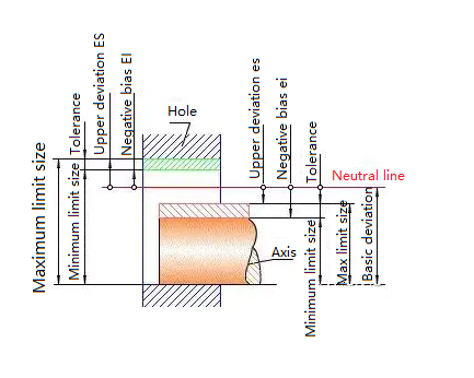
Figure 1
14. What is a standard tolerance?
Answer: Any tolerance specified by the national standard to determine the size of the tolerance zone.
15. What is coordination?
Answer: It refers to the relationship between the tolerance zones of holes and shafts that have the same basic dimensions and are combined with each other.
16. What is the base hole system?
Answer: It is the tolerance zone of the hole with a certain basic deviation, which is formed by the tolerance zone of the shaft with different basic deviations.
A system of cooperation.
17. What is a cardinal system?
Answer: It is a system in which the tolerance zone of the shaft with a certain basic deviation forms various fits with the tolerance zones of the holes with different basic deviations.
18. What is fit tolerance?
Answer: It is the variation of the allowable clearance, which is equal to the absolute value of the algebraic difference between the maximum clearance and the minimum clearance, and is also equal to the sum of the hole tolerance zone and the shaft tolerance zone that match each other.
19. What is a clearance fit?
Answer: The tolerance zone of the hole is completely above the tolerance zone of the shaft, that is, a fit with clearance (including a fit with a minimum clearance equal to zero).
20. What is an interference fit?
Answer: The tolerance zone of the hole is completely below the tolerance zone of the shaft, that is, a fit with interference (including a fit with minimum interference equal to zero).
21. What is a transition fit?
Answer: In the fit of the hole and the shaft, the tolerance zones of the hole and the shaft overlap each other. If any pair of holes and the shaft match, there may be a gap or an interference fit.
22. When the base hole system fit is H11/c11 or the base shaft system base hole system fit is C11/h11, what are the priority matching characteristics?
Answer: The gap is very large, and is used for dynamic fits that are very loose and rotate slowly; exposed components that require large tolerances and large gaps; very loose fits that require easy assembly. Equivalent to D6/dd6 of the old national standard.
23. When the base hole system fit is H9/d9 or the base shaft system base hole system fit is D9/h9, what are the priority matching characteristics?
Answer: Free-rotating fits with large clearances are used when accuracy is not an important requirement, or when there are large temperature changes, high rotational speeds or large journal pressures. Equivalent to the old national standard D4/de4.
24. When the base hole system fit is H8/f7 or the base shaft system base hole system fit is F8/h7, what are the priority matching characteristics?
Answer: The rotation fit with small clearance is used for precise rotation at medium speed and medium journal pressure; it is also used for medium positioning fit with easy assembly. Equivalent to the old national standard D/dc.
25. When the base hole system fit is H7/g6 or the base shaft system base hole system fit is G7/h6, what are the priority matching characteristics?
Answer: Sliding fits with very small clearances are used when free rotation is not expected, but free movement and sliding are required and precise positioning is required. It can also be used for clear positioning fits. Equivalent to the old national standard D/db.
26. When the base hole system fit is H7/h6; H8/h7; H9/h9; H11/h11 or the base shaft system base hole system fit is H7/h6; H8/h7; H9/h9; H11/h11, the priority matching characteristics are What?
Answer: They are all clearance positioning fits, and parts can be freely assembled and disassembled, but are generally relatively stationary during operation. The clearance at the maximum solid condition is zero, and the clearance at the minimum solid condition is determined by the tolerance class. H7/h6 is equivalent to the old national standard D/d; H8/h7 is equivalent to the old national standard D3/d3; H9/h9 is equivalent to the old national standard D4/d4; H11/h11 is equivalent to the old national standard D6/d6.
27. When the base hole system fit is H7/h6 or the base shaft system base hole system fit is K7/h6, what are the priority matching characteristics?
Answer: Transition fit, used for precise positioning. Equivalent to the old national standard D/gc.
28. When the base hole system fit is H7/n6 or the base shaft system base hole system fit is N7/h6, what are the priority matching characteristics?
Answer: Transition fit allows more precise positioning with larger interference. Equivalent to the old national standard D/ga.
29. When the base hole system fit is H7/p6 or the base shaft system base hole system fit is P7/h6, what are the priority matching characteristics?
Answer: Interference positioning fit, that is, small interference fit, is used when positioning accuracy is particularly important. It can achieve the rigidity and centering requirements of the component with the best positioning accuracy, but there are no special requirements for the inner hole with pressure, and it does not rely on The tightness of the fit transmits friction loads. Equivalent to the old national standard D/ga~D/jf. Among them, H7 less than or equal to 3mm is a transition fit.
30. When the base hole system fit is H7/s6 or the base shaft system base hole system fit is S7/h6, what are the priority matching characteristics?
Answer: Medium press fit, suitable for general steel parts; or shrink fit for thin-walled parts, used for cast iron parts to obtain the tightest fit, equivalent to the old national standard D/je.
31. When the base hole system fit is H7/u6 or the base shaft system base hole system fit is U7/h6, what are the priority matching characteristics?
Answer: Press-in fit is suitable for parts that can withstand large press-in force or shrink fit that is not suitable for withstanding large press-in force.
32. When the basic deviation of the shaft is a; b, what are the matching characteristics?
Answer: It is a clearance fit, which can produce a particularly large gap and is rarely used.
33. What are the fit characteristics when the basic deviation of the shaft is c?
Answer: It is a clearance fit, which can obtain a large gap. It is generally suitable for slow and loose dynamic fit. It is used when the working conditions are poor (such as agricultural machinery), deformation due to force, or when the surface must have a large gap to facilitate assembly. The recommended fit is H11/c11, and its higher-level fits, such as H8/c7, are suitable for tight dynamic fits where one axis operates at high temperatures, such as exhaust valves and ducts of internal combustion engines.
34. When the basic deviation of the shaft is d, what are the fit characteristics?
Answer: It is a clearance fit. The fit is generally used for IT7~IT11 levels. It is used for loose rotation fit, such as the fit between sealing cover, pulley, idle pulley, etc. and the shaft. It is suitable for large-diameter sliding bearings, such as some sliding bearings in turbines, ball mills, roll forming and heavy-duty bending machines and other heavy machinery.
35. What are the fit characteristics when the basic deviation of the shaft is e?
Answer: It is a clearance fit, mostly used in IT7~IT9 levels. It is usually suitable for support fits that require obvious clearance and easy rotation, such as large spans, multi-fulcrum supports, etc. High-grade e-axis is suitable for large, high-speed, and heavy loads. Support coordination, such as turbine generators, large electric motors, internal combustion engines, concave shafts and rocker arm supports, etc.
36. What are the fit characteristics when the basic deviation of the shaft is f?
Answer: It is a clearance fit and is mostly used for general rotational fits of IT6 to IT8 levels. When temperature has little effect, it is widely used in supports lubricated by ordinary lubricating oil (grease), such as the cooperation between the rotating shafts and sliding supports of gear boxes, small motors, pumps, etc.
37. What are the fit characteristics when the basic deviation of the shaft is g?
Answer: It is a clearance fit. The fit clearance is very small and the manufacturing cost is high. Except for precision devices with very light loads, it is not recommended for rotational fit. Mostly used in IT5~IT7 grades, most suitable for non-rotating precision sliding fits, and also used for positioning fits such as pins, such as precision connecting rod bearings, pistons, slide valves and connecting rod pins.
38. What are the fit characteristics when the basic deviation of the shaft is h?
Answer: It is a clearance fit, mostly used for IT4~IT11 levels. It is widely used for parts without relative rotation. It is used as a general positioning fit. If there is no influence of temperature deformation, it is also used for precision sliding fit.
39. What are the fit characteristics when the basic deviation of the axis is js?
Answer: It is a transition fit and is a completely symmetrical deviation (+IT/2). On average, it is a fit with a slight gap. It is mostly used for IT4-7 levels. The gap is required to be smaller than the h-axis, and a slight interference positioning fit (such as a coupling) is allowed. It can be assembled by hand or with a wooden hammer.
40. What are the fit characteristics when the basic deviation of the shaft is k?
Answer: It is a transitional fit, which is an average fit without gaps, and is suitable for IT4-IT7 levels. , recommended for positioning fits with slight interference, and for positioning fits to eliminate vibration. Usually assembled with a wooden hammer.
41. What are the fit characteristics when the basic deviation of the shaft is m?
Answer: It is a transition fit, with a small transition fit on average. Suitable for grades IT4I-T7, assembled with hammer or press, usually recommended for tight component fit. The H6/n5 fit is an interference fit.
42. What are the fit characteristics when the basic deviation of the shaft is n?
Answer: It is a transition fit. The average interference is slightly larger than the m-axis, and there is little clearance. It is suitable for IT4-IT7 levels. It is assembled with a hammer or press. It is usually recommended for tight component fit. The H6/n5 fit is an interference fit.
43. What are the fit characteristics when the basic deviation of the shaft is p?
Answer: It is an interference fit. When it is matched with H6 or H7, it is an interference fit. When it is matched with the H8 hole, it is a transition fit. For non-ferrous parts, it is a lighter press fit and is easy to disassemble when necessary. It is a standard press fit for steel, cast iron or copper or steel component assembly.
44. When the basic deviation of the shaft is r, what are the fit characteristics?
Answer: It is an interference fit. For iron parts, it is a medium-fit fit. For non-ferrous parts, it is a lightly driven fit. It can be disassembled when necessary. When matched with the H8 hole, it is an interference fit when the diameter is above 100mm, and a transition fit when the diameter is small.
45. What are the fit characteristics when the basic deviation of the shaft is s?
Answer: It is an interference fit, used for permanent and semi-permanent assembly of steel and iron parts. Can produce considerable bonding force. When elastic materials, such as light alloys, are used, the matching properties are equivalent to the P-axis of iron parts. For example, the collar is press-fitted on the shaft, valve seat, etc. When the size is large, in order to avoid damaging the mating surface, thermal expansion or cold contraction methods are required for assembly.
46. What are the matching characteristics when the basic deviation of the axis is t;u;v;x;y;z?
Answer: It is an interference fit, and the amount of interference increases sequentially. It is generally not recommended.
47. Under what circumstances should the basic axis system be used?
Answer: Directly use cold-drawn steel that is manufactured according to the tolerance zone of the reference shaft and has a certain tolerance level (generally 8 to 11 levels) without mechanical processing to make the shaft. At this time, different hole tolerance zone positions can be selected to form various matching requirements. In agricultural machinery and textile machinery, this situation is more common.
It is much more difficult to process precision shafts with dimensions less than 1 mm than to process holes of the same level. Therefore, in instrument manufacturing, watch production, radio and electronics industries, thin steel wires that have been light-rolled are usually used to directly make shafts. In this case, basic materials are used. Shaft system matching is more economical than base hole system.
From a structural point of view, one shaft matches several holes in different parts, and each has different matching requirements. In this case, the base shaft system should be considered.
48. How to cooperate with standard parts?
Answer: If it is matched with standard parts, the matching system should be determined based on the standard parts.
For example, in the rolling bearing support structure, the cooperation between the outer ring of the rolling bearing and the box hole should be based on the basic shaft system, the cooperation between the inner ring of the bearing and the journal should be based on the basic hole system, the box hole is made according to J7, and the journal is made according to k6.
49. What is the tolerance level range for grinding processing methods?
Answer: It should be IT1~IT5.
50. What is the range of tolerance level that should be adopted for the grinding processing method?
Answer: It should be IT4~IT7.
51. For diamond turning processing methods, what range of tolerance levels should be adopted?
Answer: It should be IT5~IT7.
52. What is the tolerance level range for diamond boring processing methods?
Answer: It should be IT5~IT7.
53. What is the range of tolerance level that should be adopted for the cylindrical grinding processing method?
Answer: It should be IT5~IT8.
54. For flat grinding processing method, what range of tolerance level should be adopted?
Answer: It should be IT5~IT8.
55. For broaching processing method, what range of tolerance level should be adopted?
Answer: It should be IT5~IT8.
56. What is the tolerance level range for fine turning and fine boring processing methods?
Answer: It should be IT7~IT9.
57. What is the tolerance level range for reaming processing methods?
Answer: It should be IT6~IT10.
58. For milling processing methods, what range of tolerance levels should be adopted?
Answer: It should be IT8~IT11.
59. For planing and inserting processing methods, what range of tolerance levels should be adopted?
Answer: It should be IT10~IT11.
60. What is the tolerance level range for rolling and extrusion processing methods?
Answer: It should be IT10~IT11.
61. For rough turning processing methods, what range of tolerance levels should be adopted?
Answer: It should be IT10~IT12.
62. For rough boring processing method, what range of tolerance level should be adopted?
Answer: It should be IT10~IT12.
63. What is the tolerance level range for drilling processing methods?
Answer: It should be IT10~IT13.
64. What is the tolerance level range for stamping processing methods?
Answer: It should be IT10~IT14.
65. What is the tolerance level range for sand casting processing methods?
Answer: It should be IT14~IT15.
66. What is the tolerance level range for metal mold casting processing methods?
Answer: It should be IT14~IT15.
67. For forging processing method, what range of tolerance level should be adopted?
Answer: It should be IT15~IT16.
68. For gas cutting processing methods, what range of tolerance levels should be adopted?
Answer: It should be IT15~IT18.
69. How many methods are there to determine the basic deviation?
Answer: There are three methods to determine the basic deviation: experimental method, calculation method and analogy method.
70. What is the experimental method?
Answer: The test method is to use the test method to determine the type of combination that meets the working performance of the product. It is mainly used in some key institutions in the aerospace, aviation, national defense, nuclear industry and railway transportation industries, which have a large impact on product performance and lack of experience. important and critical cooperation. This method is relatively reliable. The disadvantage is that it requires testing, high cost and long cycle. Less commonly used.
71. What is a calculation method?
Answer: The calculation method is to determine the type of coordination through theoretical calculation according to the usage requirements. Its advantage is that the theoretical basis is sufficient and the cost is lower than the experimental method. However, because the theoretical calculation cannot fully consider various practical factors of the working environment of the machine and equipment, the design plan is not as accurate as that determined by the experimental method. For example, when using the calculation method to determine the type of clearance fit of a sliding bearing, the minimum allowable clearance can be calculated based on the liquid lubrication theory, and the appropriate type of fit can be selected from the standard accordingly; the calculation method is used to determine the process that completely relies on interference to transmit the load. When choosing the type of interference fit, according to the size of the load to be transmitted, according to the elastic and plastic deformation theory, the minimum interference required can be calculated, and the appropriate type of interference fit can be selected based on this. At the same time, it can be checked whether the material strength of the part can withstand the requirements of the type of fit. The maximum interference produced. Since there are many factors that affect fitting clearance and interference, theoretical calculations can only be approximate.
72. What is analogy?
Answer: The analogy method is to use the cooperation that has been verified in production practice in the same type of machine or mechanism as the design task as a reference, and determine the coordination based on the actual use requirements and application conditions of the designed product. This method is the most widely used, but requires designers to have sufficient reference materials and considerable experience. Factors that should be considered when determining fit using the analogy method are as follows:
The size of the force. When the force is large, the fit will tend to be tight, that is, the interference amount of the interference fit should be appropriately increased, the clearance amount of the clearance fit should be reduced, and a transition fit with a high probability of interference should be selected.
Disassembly and assembly conditions and structural features. For fits that are frequently disassembled and assembled, the fits should be looser than those with the same task that are not frequently disassembled and assembled. Fits that are difficult to assemble should also be slightly looser.
Combine length and shape errors. The longer the fit length, the tighter the fit actually formed due to the presence of form and position errors compared with a fit with a short combination length. Therefore, it is advisable to choose a suitably loose fit.
Material, temperature. When the materials of the corresponding parts are different (linear expansion coefficients are greatly different) and the operating temperature is significantly different from the standard temperature +20°C, the influence of thermal deformation must be considered. Effect of assembly deformation.
73. When the tolerance level is level 5, what are the applications?
Answer: It is mainly used in situations where the fit tolerance and geometric tolerance are very small, and the fit properties are stable. It is generally used in important parts such as machine tools, engines, and instruments. Such as the box hole matched with D-class rolling bearings; the machine tool spindle, machine tool tailstock and sleeve matched with E-class rolling bearings, journals in precision machinery and high-speed machinery, precision screw diameters, etc.
74. When the tolerance level is level 6, what are the applications?
Answer: The matching properties can achieve high uniformity, such as holes and journals that match E-class rolling bearings; shaft diameters connected to gears, worm gears, couplings, pulleys, cams, etc., and machine tool screw shaft diameters; The radial drill column; the outer diameter size of the guide in the machine tool fixture; the reference hole of the 6th grade precision gear, and the 7th and 8th grade gear datum axis.
75. When the tolerance level is level 7, what are the applications?
Answer: The accuracy of level 7 is slightly lower than that of level 6, and the application conditions are basically similar to level 6. It is more commonly used in general machinery manufacturing. Such as coupling, pulley, cam and other apertures; machine tool chuck seat hole, fixed drill bushing in the fixture, replaceable drill bushing; 7th and 8th grade gear reference hole, 9th and 10th grade gear reference shaft.
76. When the tolerance level is level 8, what are the applications?
Answer: It is a medium precision in machine manufacturing. Such as the dimensions of the bearing seat bushing along the width direction, the reference hole of the 9th to 12th grade gear; the reference shaft of the 11th to 12th grade gear.
77. When the tolerance level is 9 to 10, what are the applications?
Answer: Mainly used in mechanical manufacturing for the outer diameter and hole of the shaft sleeve; the control part and the shaft; the hollow shaft pulley and the shaft; the single key and the spline.
78. When the tolerance level is 11 to 12, what are the applications?
Answer: The fit accuracy is very low, and a large gap may occur after assembly. It is suitable for situations where there are basically no fit requirements. Such as the flange and stop on machine tools; sliding and sliding gears; dimensions between processes during processing; matching parts for stamping processing; the connection between the wrench hole and the wrench seat in machine tool manufacturing.
79. How to choose clearance fit in actual design?
Answer: See Figure 2
Hinges for crane hooks Flanges with tongue and groove Exhaust valves and guides for internal combustion engines
Coordination of pulley and shaft Coordination of internal combustion engine main shaft
Fitting of gear bushing and shaft Fitting of drill bushing and bushing
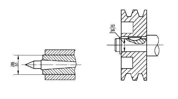
Figure 2
The fit of the top sleeve of the lathe tailstock and the fit of the pulley and the shaft
80. How to choose transition fit in actual design?
Answer: See Figure 3
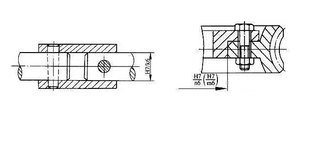
Figure 3
The fit of the rigid coupling and the fit of the bronze rim and spokes of the worm gear
81. How to choose interference fit in actual design?
Answer: See Figure 4
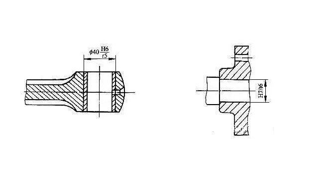
Figure 4
82. How to mark linear dimensional tolerances on parts drawings?
Answer: See Figure 5
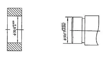
Figure 5
83. How to mark linear dimensional tolerances on assembly drawings?
Answer: See Figure 6
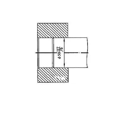
Figure 6
84. How to mark the linear dimensional tolerance of standard parts?
Answer: See Figure 7
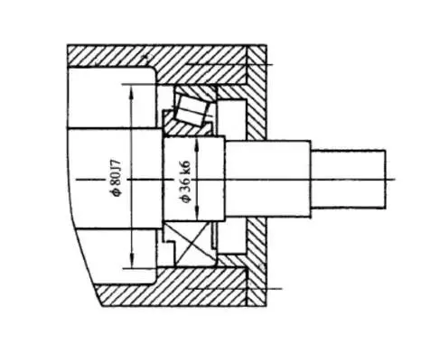
Figure 7
85. What are the requirements for linear dimension tolerance marking?
Answer: The tolerance code is the same as the basic size number.
When the limit deviation is used to mark linear dimensional tolerances, the upper and lower deviation numbers are one size smaller than the basic size number, and the decimal points of the upper and lower deviations must be aligned and marked with positive and negative signs.
One of the deviations is zero, marked with a "0" and aligned with the other deviation of single digits.
The lower deviation bottom line and the basic dimension are marked on the same bottom line.
When the upper and lower deviation values are equal, the deviation is only written once, and a "+/-" sign is added between the deviation and the basic size, and the font size of both is the same.
86. What is a cone fit?
Answer: The basic cone is the mutual relationship formed by the different combinations between the inner and outer cone diameters of the same cone. The mating feature of the conical fit is to form a gap or interference through the axial position specified by the inner and outer cones combined with each other. The gap or interference acts in the direction perpendicular to the cone surface, but is given and measured perpendicular to the cone axis; for cones with a taper less than or equal to 1:3, the values are given perpendicular to the cone surface and perpendicular to the cone axis. The difference between them is negligible. According to different methods of determining the axial position of the combined inner and outer cones, the cone fit is divided into two types: structural cone fit and displacement cone fit.
87. What is a structural cone fit?
Answer: The fit is obtained by determining the relative axial positions of the inner and outer cones based on the structure itself or the size of the structure.
88. What is a displacement cone fit?
Answer: The fit obtained by specifying the axial displacement or the axial force that generates the axial displacement is used to determine the relative axial position of the inner and outer cones.
89. What three items does the standard tolerance series consist of?
Answer: It is divided into tolerance levels, tolerance units and basic dimensions.
90. What is a general tolerance?
Answer: It refers to the tolerance that can be achieved by the general processing capabilities of machine tool equipment under ordinary process conditions in the workshop.
91. What does GB/T1804-1992 specify for the general tolerances of linear dimensions?
Answer: A total of 4 tolerance levels are specified: f, m, c and v. The letter f means precision level, m means medium level, c means rough level and v means the coarsest level. Tolerance levels f, m, c and v are equivalent to IT12, IT14, lt16 and IT17 respectively.
92. What is the table of limit deviation values for general tolerances of linear dimensions?
Answer: See Table 1
Table 1
| Tolerance class | Size segmentation | |||||||
| 0.5~3 | >3~6 | >6-30 | >30 ~120 | >120 ~100 | >100 ~10000 | >1000 ~2000 | >2000 ~1000 | |
| f (precision) | ±0.05 | ±0.05 | ±0. 1 | H0. 15 | ±0.2 | ±0.3 | ±0 .5 | - |
| m (medium level) | ±0.1 | ±0.1 | ±0.2 | ±0.3 | ±0.5 | ±0.8 | ±1.2 | ±2 |
| c (rough grade) | ±0.2 | 10,3 | 0.5 | ±10.8 | ±1.2 | ±2 | ±3 | ±4 |
| v (the coarsest level) | - | ±0.5 | ±1 | ±1.5 | ±2.5 | ±4 | ±6 | ±8 |
93. What is the numerical table of limit deviations of rounding radius and chamfering height?
Answer: See Table 2
Table 2
| Tolerance class | Size segmentation | |||
| 0.5~3 | >3~6 | >6~30 | >30 | |
| f (precision) | ±0.2 | ±0.5 | ±1 | ±2 |
| m (medium level) | ||||
| c (rough grade) | ±0.4 | ±1 | ±2 | ±4 |
| v (the coarsest level) | ||||
94. What should we pay attention to when using clearance fit?
Answer: The datum hole H (or datum axis h) forms a clearance fit with the axes a~h (or holes A~H) of the corresponding tolerance level. There are 11 types in total, among which
The gap composed of H/a (or A/h) is the largest, and the matching gap of H/h is the smallest.
H/a (A/h), H/b (B/h), H/c (C/h) fit. The gaps between these three fits are very large and are not commonly used. It is generally used in machines with poor working conditions that require flexible movement, or in situations where the force and deformation are large, and the shaft needs to ensure a large clearance when working at high temperatures.
H/d (D/h) and H/e (E/h) fits. These two fits have large gaps and are used for supports that are not demanding and easy to rotate. Among them, H/d (D/h) is suitable for loose transmission cooperation, such as the cooperation between sealing cover, pulley and idle pulley and the shaft. It is also suitable for the matching of large-diameter sliding bearings, such as sliding bearings of heavy machinery such as ball mills and rolling mills, and is suitable for grades IT7 to IT11. For example, the fit of pulleys and shafts.
H/f (F/h) fit. The clearance of this fit is moderate. It is mostly used for general transmission fit of IT7~IT9, such as the fit of rotating shafts and sliding supports of gear boxes, small motors, pumps, etc.
H/g (G/h) fit. This type of fit has a very small clearance. Except for precision mechanisms with very light loads, rotational fit is generally not required. It is mostly used for IT5 ~ IT7 levels and is suitable for precision fit of reciprocating swing and sliding. For example, the fit between drill bushing and bushing.
H/h fit. The minimum clearance of this fit is zero. It is used for IT4~IT11 levels. It is suitable for positioning fit without relative rotation but with centering and guiding requirements. If there is no influence of temperature or deformation, it can also be used for sliding fit. It is recommended. Compatible with H6/h5, H7/h6, H8/h7, H9/h9 and H11/h11.
95. What should you pay attention to when transitioning?
Answer: The reference hole H forms a transition fit with the basic deviation code j~n of the corresponding tolerance grade axis (n forms an interference fit with the high-precision hole).
H/j and H/js fits. These two transition fits have more opportunities to obtain gaps. They are mostly used in IT4~IT7 levels. They are suitable for positioning fits that require the gap to be smaller than h and allow a slight interference, such as couplings, The cooperation between the ring gear and the steel hub and the rolling bearing and the box, etc.
H/k fit, the average gap obtained by this fit is close to zero, the centering is good, the contact stress on the parts after assembly is small, and they can be disassembled. It is suitable for IT4~IT7 levels, such as the fit of rigid couplings.
H/m and H/n combinations, these two types of combinations have more opportunities to obtain interference, have good centering and tight assembly, and are suitable for IT4~IT7.
96. What should you pay attention to when making an interference fit?
Answer: The reference hole H forms an interference fit with the basic deviation code p~zc of the corresponding tolerance grade axis (p, r form a transition fit with the lower precision H hole).
H/p and H/r fits. These two fits are interference fits at high tolerance levels. They can be assembled by hammering or press, and should only be disassembled during overhaul. It is mainly used for positioning and matching with high centering accuracy, sufficient rigidity of parts, and impact loads. It is mostly used for IT6~IT8 levels.
H/s and H/t fits, these two fits are medium interference fits, and most use IT6 and IT7 levels. For permanent or semi-permanent bonding of steel parts. Without auxiliary parts, medium loads can be transferred directly by relying on the bonding force generated by interference. Generally, it is assembled by pressure method, but also by cold shaft or hot sleeve method, such as the assembly of cast iron wheels and shafts, and the fit of columns, pins, shafts, sleeves, etc. that are pressed into holes.
H/u, H/v, H/x, H/y, H/z fits, these are large interference fits, the amount of interference increases in sequence, and the ratio of interference to diameter is above 0.001. They are suitable for transmitting large torque or withstanding large impact load. They rely entirely on the bonding force generated by interference to ensure a solid connection. They are usually assembled using hot sleeve or cold shaft methods. The cast steel wheels and high manganese steel hoops of trains should be matched with H7/u6 or even H6/u5. Due to the large interference, the parts are required to be made of good material and have high strength, otherwise the parts will be squeezed and cracked. Therefore, they must be used with caution and generally must be tested before being put into production. Before assembly, selection is often required to make the interference of a batch of accessories consistent and moderate.
97. Why is the base hole system preferred?
Answer: Because it is difficult to process holes, changing the size of the holes requires changing the number of tools and measuring tools. Changing the size of the shaft will not change the number of tools and measuring tools.
98. How are tolerance levels applied?
Answer: See Table 3
table 3
| Tolerance Class/Application | 01 | 0 | 1 | 2 | 3 | 4 | 5 | 6 | 7 | 8 | 9 | 10 | 11 | 12 | 13 | 14 | 15 | 16 | 17 | 18 |
| Block gauge | ||||||||||||||||||||
| Gauges | ||||||||||||||||||||
| Matching size | ||||||||||||||||||||
| Special precision parts | ||||||||||||||||||||
| Non-matching dimensions | ||||||||||||||||||||
| Raw materials | ||||||||||||||||||||
99. How do usage requirements determine the type of fit?
Answer: When the hole and shaft move or rotate relative to each other, clearance fit must be selected. Relative movement selects a mate with a smaller gap, and relative rotation selects a mate with a larger gap.
When there are no connecting parts such as keys, pins, screws, etc. between the hole and the shaft, and transmission can only be achieved by the cooperation between the hole and the shaft, an interference fit must be selected.
The characteristic of transition fit is that gaps and interference may occur, but the amount of gap or interference is relatively small. Therefore, when there is no relative movement between parts, the concentricity requirements are high, and power is not transmitted through fit, transition fit is often chosen.
100. What are the principles for selecting dimensional tolerances and fits?
Answer: The principle of selection is to obtain the best technical and economic benefits while meeting the use requirements.