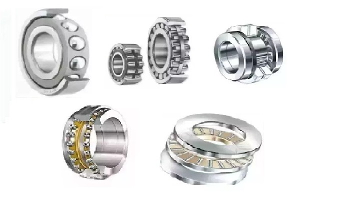
1. Angular Contact Bearing Product Overview
Rolling bearings are crucial components of rotating equipment. Both the axial and radial loads of the equipment are transmitted to the equipment support parts through the bearings. Generally, we select bearings according to different working conditions, such as load conditions, bearing arrangements, types of lubrication, etc. The correct selection and use of bearings have a significant impact on whether the bearings can reach their expected service life.
Angular contact bearings are rolling bearings that can withstand both radial and axial loads simultaneously. Their core feature is the single sided contact angle design. Compared with deep groove ball bearings, angular contact bearings have a single sided contact angle. Therefore, a single row angular contact bearing can only bear an axial load in one direction or a combined load. Due to the influence of the contact angle, an axial component force will also be generated after bearing the radial load. So, generally, two bearings are used in opposition or more than two are used in pairs. This type of bearing is suitable for scenarios with high rigidity, high precision, and combined loads, such as machine tool spindles, gearboxes, and motors.
2. Assembly Forms and Codes of Angular Contact Bearings (Refer to Standard GB/T 272)
a) Paired Assembly (Matching)
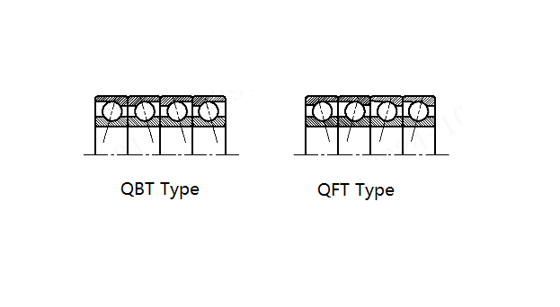
b) Triple Assembly
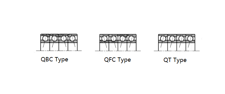
c) Quadruple Assembly
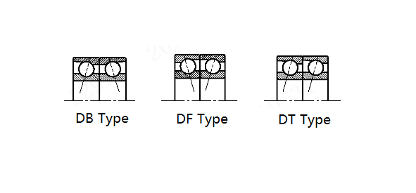
3. Understanding the Configuration of Matched Bearings (e.g., Paired assembled Bearings)
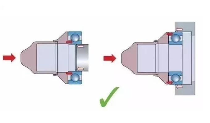
It is of great importance to understand the configuration of matched bearings during the selection and assembly process. Incorrect installation and lack of understanding of equipment applications may lead to problems such as slipping or overheating during equipment operation. The following analysis takes paired assembled bearings as an example:
1) Back - to - Back Arrangement (DB type)
Also known as the O - shaped arrangement (the bearing model generally contains the DB mark when selecting the bearing). This arrangement can provide maximum stability and rigidity. In this arrangement, the end faces of the inner rings are in contact with each other through pre - compression to achieve pre - load, and it can bear axial loads in both directions as well as radial loads.
For a back - to - back combination, the force on the inner ring of the bearing pushes the rolling elements towards the outer ring. The outer ring exerts a reaction force to the applied load, and this load is towards the centerline of the shaft. According to the contact angle, the reaction forces of the two bearings will diverge. The distance between the two reaction forces is L. Since L is greater than the width of the bearing, the back - to - back arrangement has a better rated resistance to the moment in the bearing system.
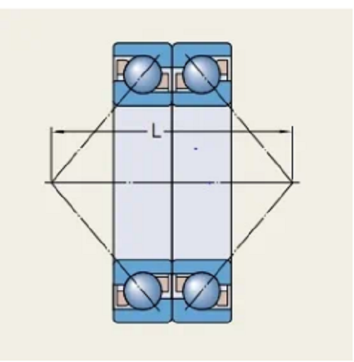
Advantages of DB Type Configuration:
- High rigidity
- Can bear moment loads.
2. Face - to - Face Arrangement (DF type)
Also known as the X arrangement (the bearing model generally contains the DF mark when selecting the bearing). This arrangement can tolerate a certain amount of misalignment error, but it cannot support moment loads as effectively as the back - to - back arrangement. If misalignment between bearing positions cannot be avoided, it is recommended to use a face - to - face bearing arrangement.
In this arrangement, compared with the back - to - back arrangement, the reaction load lines converge inward, the span L decreases, so the rigidity weakens, and the misalignment tolerance ability increases.
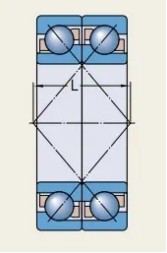
Advantages of DF Type Configuration:
- Can compensate for a certain amount of misalignment error, but the structural rigidity is not as good as that of the DB type.
|
Assembly Form |
Code |
Arrangement Characteristics |
Advantages |
Applicable Scenarios |
|
Back - to - Back (DB type) |
DB |
Inner ring end faces are pre - tightened and in contact, with a large span L |
High rigidity, strong moment - resistance ability |
High - precision machine tools, spindles |
|
Face - to - Face (DF type) |
DF |
Reaction force lines converge, with a small span L |
Tolerates misalignment error |
Occasions with installation deviations |
|
Tandem (DT type) |
DT |
Axially stacked arrangement |
Bears unidirectional heavy loads |
Unidirectional thrust - load equipment |
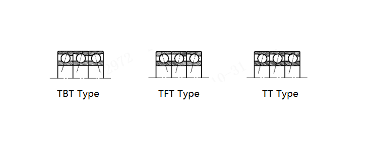
Note: Triple (TBT/TFT/ TT type) and quadruple assemblies (QBC/QFC/QT type) are suitable for higher loads or complex working conditions.
4. Key Parameters and Technical Requirements
Pre - load, Pre - clearance and Protrusion of Angular Contact Bearings
1. JB/T 2974 stipulates the representation methods of pre - load and pre - clearance of assembled bearings:
a) Pre - load
(G)A --- Light pre - load;
(G)B --- Medium pre - load;
(G)C --- Heavy pre - load.
Note: The symbol (G) in the code can be omitted.
For special pre - loads, the code representation method is GXXX. For example, for a special pre - load of 325N, the code is G325.
b) Pre - clearance
CA --- Smaller axial clearance
CB --- Medium axial clearance
CC --- Larger axial clearance
|
Code |
Axial Clearance |
Applicable Scenarios |
|
CA |
Smaller |
High - precision positioning |
|
CB |
Medium |
General working conditions |
|
CC |
Larger |
High - temperature or expansion compensation |
2. Protrusion
The protrusions b and f of a single - set bearing in an assembled bearing and the protrusion after configuration (taking DB and DF types as examples) are shown in the figure:
Protrusion of single bearing
The protrusion of an assembled bearing
The sum of the protrusion deviations of two adjacent bearings in an assembled bearing, △b1 + △b2 or △f1 + △f2 (for back - to - back and face - to - face configurations), and the difference of the protrusion deviations, △b1 - △f2 or △f1 - △b2 (for tandem configuration) shall comply with the following regulations (unit: μm):
|
d |
The sum (or difference) of the protrusion deviations of two adjacent sets of bearings |
||||||||
|
Bearing tolerance grade |
|||||||||
|
6 |
5 |
4 |
2 |
||||||
|
> |
|
min |
max |
min |
max |
min |
max |
min |
max |
|
10° |
18 |
-1.5 |
+1.5 |
-1 |
+1 |
-1 |
+1 |
-1 |
+1 |
|
18 |
30 |
-1.5 |
+1.5 |
-1 |
+1 |
-1 |
+1 |
-1 |
+1 |
|
30 |
50 |
-2 |
+2 |
-1.5 |
+1.5 |
-1 |
+1 |
-1 |
+1 |
|
50 |
80 |
-2 |
+2 |
-1.5 |
+1.5 |
-1.5 |
+1.5 |
-1.5 |
+1.5 |
|
80 |
120 |
-3 |
+3 |
-2 |
+2 |
-1.5 |
+1,5 |
-1.5 |
+1.5 |
|
120 |
150 |
-3 |
+3 |
-2 |
+2 |
-1.5 |
+1.5 |
-1.5 |
+1.5 |
|
150 |
180 |
-4 |
+4 |
-3 |
+3 |
-2 |
+2 |
-2 |
+2 |
|
180 |
250 |
-4 |
+4 |
-3 |
+3 |
-2 |
+2 |
-2 |
+2 |
|
*Including 10mm. |
|||||||||
For universal - assembled bearings, the protrusions of the two end faces of a single - set bearing should be equal, that is, b = f.
3. Spacer Ring
Inner and outer spacer rings can be used between the two bearings in an assembled bearing, as shown in the figure:
The width tolerance △H of the inner and outer spacer rings shall comply with the regulations in the following table. The parallelism error of the two end faces should not exceed 1/2 of the width tolerance.
|
d/mm |
Width tolerance △n/pm |
||
|
> |
≤ |
min |
max |
|
10* |
55 |
-1 |
+1 |
|
55 |
150 |
-1.5 |
+1.5 |
|
150 |
220 |
-2 |
+2 |
|
*Including 10mm. |
|||
The spacer ring is made of high carbon chromium bearing steel GCr15 or materials with equivalent performance. The heat - treatment hardness is 45HRC - 60HRC, or the same as the hardness range requirements of the bearing rings.
5. Measurement Method of the Protrusion of Assembled Bearings
The measurement method of the protrusion of assembled bearings is shown in the figure (taking the measurement of the protrusion b of the back end face as an example).
Install the inner ring of the bearing onto the mandrel to ensure the correct horizontal positioning of the inner ring end face. Rotate the inner ring to make the raceway of the ring and the rolling elements in a normal contact state. Measure the height difference between the back end face of the outer ring and the end face of the inner ring, which is the protrusion at a certain point. Measure the protrusions at multiple points and calculate the average value, which is the average protrusion of the measured bearing. When the measurement load applied on the end face of the outer ring reaches the specified pre - load, the protrusion is 0. The measurement standards for other items shall comply with the provisions of GB/T 307.2.

Schematic diagram of the protrusion measurement method
6. Marking and Labeling
In addition to the markings specified in GB/T 24605, assembled bearings are also marked as follows for correct use:
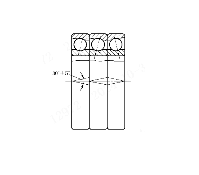
a) On the outer diameter surface of assembled bearings (except universal - assembled bearings), angular lines (V - shaped lines) with an included angle of 30° are marked. The direction of the included angle of the angular lines points to the direction of the axial load acting on the inner ring of the bearing (when bearing bidirectional axial loads, the included angle points to the direction of the larger axial load), as shown in the figure:
Marking of the assembled angular lines
b) On the outer diameter surface of a single set bearing of a universal assembled bearing, angular lines with an included angle of 30° are marked. The vertex of the included angle of the angular lines points in the same direction as the contact angle of the bearing (i.e., the direction of the axial load acting on the inner ring of the bearing), as shown in the figure.
Marking of the contact angle angular lines
c) For individual bearings in assembled bearings with a tolerance grade of 4 or above, the maximum points of the thickness variation Ki between the inner ring raceway and the inner hole and the thickness variation Ke between the outer ring raceway and the outer surface shall be marked at the corresponding positions on the end faces of the inner and outer rings respectively. The marking symbol is “*”.
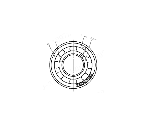
Marking of Ki, Ke, △dmp, and △Dmp
d) The average inner diameter deviation △dmp and the average outer diameter deviation △Dmp (unit: μm) of individual bearings in an assembled bearing are marked on the end faces of the inner and outer rings. For universal - assembled bearings in individual packaging, the corresponding markings are on the bearing model on the packaging box.
7. Reference Values of Pre - load for Matched Bearings
The light, medium, and heavy pre - load values of back - to - back (DB type) or face - to - face (DF type) matched bearings are shown in the following table:
Table A Pre - load of matched bearings (DB and DF types) with a nominal contact angle a = 15°
Unit: N
|
Inner diameter Code |
(B)71800 C |
(B)71900 C |
(B)7000 C |
(B)7200 C |
||||||||
|
A |
B |
C |
A |
B |
C |
A |
B |
C |
A |
B |
C |
|
|
6 |
- |
- |
- |
- |
- |
- |
7 |
13 |
25 |
- |
- |
- |
|
|
- |
- |
- |
- |
- |
- |
h |
18 |
35 |
12 |
24 |
48 |
|
8 |
- |
- |
- |
- |
- |
- |
10 |
20 |
40 |
14 |
28 |
56 |
|
9 |
- |
- |
- |
- |
- |
- |
10 |
20 |
40 |
15 |
30 |
60 |
|
00 |
10 |
30 |
60 |
10 |
20 |
40 |
15 |
30 |
60 |
20 |
40 |
80 |
|
01 |
11 |
33 |
66 |
10 |
20 |
40 |
15 |
30 |
60 |
20 |
40 |
80 |
|
02 |
12 |
36 |
72 |
15 |
30 |
60 |
20 |
40 |
80 |
30 |
60 |
120 |
|
03 |
12 |
37 |
75 |
15 |
30 |
60 |
25 |
50 |
100 |
35 |
70 |
140 |
|
04 |
20 |
60 |
120 |
25 |
50 |
100 |
35 |
70 |
140 |
45 |
90 |
180 |
|
05 |
22 |
66 |
132 |
25 |
50 |
100 |
35 |
70 |
140 |
50 |
100 |
200 |
|
06 |
23 |
70 |
140 |
25 |
50 |
100 |
50 |
100 |
200 |
90 |
180 |
360 |
|
07 |
25 |
75 |
150 |
35 |
70 |
140 |
60 |
120 |
240 |
120 |
240 |
480 |
|
08 |
26 |
78 |
155 |
45 |
90 |
180 |
60 |
120 |
240 |
150 |
300 |
600 |
|
09 |
27 |
80 |
160 |
50 |
100 |
200 |
110 |
220 |
440 |
160 |
320 |
640 |
|
10 |
40 |
120 |
240 |
50 |
100 |
200 |
110 |
220 |
440 |
170 |
340 |
680 |
|
11 |
55 |
165 |
330 |
70 |
140 |
280 |
150 |
300 |
600 |
210 |
420 |
840 |
|
12 |
70 |
210 |
420 |
70 |
140 |
280 |
150 |
300 |
600 |
250 |
500 |
1000 |
|
13 |
71 |
215 |
430 |
80 |
160 |
320 |
160 |
320 |
640 |
290 |
580 |
1160 |
|
14 |
73 |
220 |
440 |
130 |
260 |
520 |
200 |
400 |
800 |
300 |
600 |
1200 |
|
15 |
76 |
225 |
450 |
130 |
260 |
520 |
200 |
400 |
800 |
310 |
620 |
1 240 |
|
16 |
78 |
235 |
470 |
140 |
280 |
560 |
240 |
480 |
960 |
370 |
740 |
1 480 |
|
17 |
115 |
345 |
690 |
170 |
340 |
680 |
250 |
500 |
1000 |
370 |
740 |
1 480 |
|
18 |
116 |
350 |
700 |
180 |
360 |
720 |
300 |
600 |
1 200 |
480 |
960 |
1 920 |
|
19 |
117 |
355 |
710 |
190 |
380 |
760 |
310 |
620 |
1 240 |
520 |
1 040 |
2 080 |
|
20 |
120 |
360 |
720 |
230 |
460 |
920 |
310 |
620 |
1 240 |
590 |
1180 |
2 360 |
|
21 |
130 |
390 |
780 |
230 |
460 |
920 |
360 |
720 |
1 440 |
650 |
1 300 |
2 600 |
|
22 |
160 |
500 |
1 000 |
230 |
460 |
920 |
420 |
840 |
1 680 |
670 |
1340 |
2 680 |
|
24 |
180 |
550 |
1 100 |
290 |
580 |
1160 |
430 |
860 |
1 720 |
750 |
1500 |
3 000 |
|
26 |
210 |
620 |
1 230 |
350 |
700 |
1 400 |
560 |
1120 |
2 240 |
800 |
1 600 |
3 200 |
|
28 |
240 |
720 |
1 440 |
360 |
720 |
1 440 |
570 |
1140 |
2 280 |
一 |
- |
- |
|
30 |
270 |
820 |
1 630 |
470 |
940 |
1 880 |
650 |
1 300 |
2 600 |
- |
- |
- |
|
32 |
280 |
850 |
1 700 |
490 |
980 |
1 960 |
730 |
1 460 |
2 920 |
- |
- |
- |
|
34 |
一 |
- |
- |
500 |
1.000 |
2 000 |
800 |
1 600 |
3 200 |
- |
- |
- |
|
36 |
- |
- |
- |
630 |
1 260 |
2 520 |
900 |
1 800 |
3 600 |
- |
- |
- |
|
38 |
- |
- |
- |
640 |
1280 |
2 560 |
950 |
1 900 |
3 800 |
- |
- |
- |
|
40 |
- |
- |
- |
800 |
1600 |
3 200 |
1100 |
2 200 |
4 400 |
- |
- |
- |
|
44 |
- |
- |
- |
850 |
1700 |
3 400 |
1 250 |
2 500 |
5 000 |
- |
- |
- |
|
48 |
- |
- |
- |
860 |
1720 |
3 440 |
1 300 |
2 600 |
5 200 |
- |
- |
- |
|
52 |
- |
- |
- |
1050 |
2110 |
4 220 |
1 550 |
3 100 |
6 200 |
- |
- |
- |
|
56 |
- |
- |
- |
1 090 |
2 180 |
4360 |
- |
- |
- |
- |
- |
- |
|
60 |
- |
- |
- |
1 400 |
2 800 |
5 600 |
- |
- |
- |
- |
- |
- |
|
64 |
- |
- |
- |
1 400 |
2 800 |
5 600 |
- |
- |
- |
- |
- |
|
|
Inner diameter Code |
(B)71900 AC |
(B)7000 AC |
(B)7200 AC |
7200 B,7300 B |
||||||||
|
A |
B |
C |
A |
B |
C |
A |
B |
C |
A |
B |
C |
|
|
8 |
- |
- |
- |
20 |
40 |
80 |
- |
- |
- |
- |
- |
- |
|
9 |
- |
- |
- |
20 |
40 |
80 |
- |
- |
- |
- |
- |
- |
|
00 |
15 |
30 |
60 |
25 |
50 |
100 |
35 |
70 |
140 |
80 |
330 |
550 |
|
01 |
15 |
30 |
60 |
25 |
50 |
100 |
35 |
70 |
140 |
80 |
330 |
560 |
|
02 |
25 |
50 |
100 |
30 |
60 |
120 |
45 |
90 |
180 |
80 |
330 |
660 |
|
03 |
25 |
50 |
100 |
40 |
80 |
160 |
60 |
120 |
240 |
80 |
330 |
660 |
|
04 |
35 |
70 |
140 |
50 |
100 |
200 |
70 |
140 |
280 |
120 |
480 |
970 |
|
05 |
40 |
80 |
160 |
60 |
120 |
240 |
80 |
150 |
320 |
120 |
480 |
970 |
|
06 |
40 |
80 |
160 |
90 |
180 |
360 |
150 |
300 |
600 |
120 |
480 |
970 |
|
07 |
60 |
120 |
240 |
90 |
180 |
360 |
190 |
380 |
760 |
160 |
630 |
1 280 |
|
08 |
70 |
140 |
280 |
100 |
200 |
400 |
240 |
480 |
960 |
160 |
630 |
1280 |
|
09 |
80 |
160 |
320 |
170 |
340 |
680 |
260 |
520 |
1 040 |
160 |
630 |
1280 |
|
10 |
80 |
160 |
320 |
180 |
360 |
720 |
260 |
520 |
1 040 |
160 |
630 |
1280 |
|
11 |
120 |
240 |
480 |
230 |
460 |
920 |
330 |
660 |
1 320 |
380 |
1 500 |
3 050 |
|
12 |
120 |
240 |
480 |
240 |
480 |
960 |
400 |
800 |
1600 |
380 |
1 500 |
3 050 |
|
13 |
120 |
240 |
480 |
240 |
480 |
960 |
450 |
900 |
1800 |
380 |
1500 |
3 050 |
|
14 |
200 |
400 |
800 |
300 |
600 |
1 200 |
480 |
960 |
1920 |
380 |
1500 |
3 050 |
|
15 |
210 |
420 |
840 |
310 |
620 |
1 240 |
500 |
1 000 |
2 000 |
380 |
1 500 |
3 050 |
|
16 |
220 |
440 |
880 |
390 |
780 |
1 560 |
580 |
1160 |
2.320 |
380 |
1 500 |
3 050 |
|
17 |
270 |
540 |
1 080 |
400 |
800 |
1 600 |
600 |
1 200 |
2 400 |
410 |
1600 |
3 250 |
|
18 |
280 |
560 |
1 120 |
460 |
920 |
1 840 |
750 |
1 500 |
3 000 |
410 |
1 600 |
3 250 |
|
19 |
290 |
580 |
1-160 |
480 |
960 |
1 920 |
850 |
1 700 |
3.400 |
410 |
1 600 |
3 250 |
|
20 |
360 |
720 |
1 440 |
500 |
1 000 |
2 000 |
950 |
1 900 |
3 800 |
410 |
1 600 |
3 250 |
|
21 |
360 |
720 |
1 440 |
560 |
1120 |
2 240 |
1 000 |
2 000 |
4 000 |
410 |
1600 |
3 250 |
|
22 |
370 |
740 |
1 480 |
650 |
1 300 |
2 600 |
1 050 |
2100 |
4 200 |
410 |
1 600 |
3 250 |
|
24 |
450 |
900 |
1 800 |
690 |
1 380 |
2 760 |
1 200 |
2 400 |
4 800 |
410 |
1600 |
3.250 |
|
26 |
540 |
1 080 |
2 160 |
900 |
1 800 |
3 600 |
1 250 |
2 500 |
5 000 |
540 |
2 150 |
4 300 |
|
28 |
560 |
1 120 |
2 240 |
900 |
1 800 |
3 600 |
- |
- |
- |
540 |
2 150 |
4 300 |
|
30 |
740 |
1 480 |
2 960 |
1 000 |
2 000 |
4 000 |
- |
- |
- |
540 |
2 150 |
4 300 |
|
32 |
800 |
1 500 |
3 200 |
1 150 |
2 300 |
4 600 |
- |
- |
- |
540 |
2 150 |
4 300 |
|
34 |
800 |
1 500 |
3 200 |
1 250 |
2 500 |
5 000 |
- |
- |
- |
540 |
2 150 |
4 300 |
|
36 |
1 000 |
2.000 |
4 000 |
1 450 |
2 900 |
5 800 |
- |
- |
- |
540 |
2 150 |
4 300 |
|
38 |
1 000 |
2 000 |
4 000 |
1 450 |
2 900 |
5 800 |
- |
一 |
- |
940 |
3 700 |
7 500 |
|
40 |
1 250 |
2 500 |
5 000 |
1 750 |
3 500 |
7.000 |
- |
- |
- |
940 |
3 700 |
7 500 |
|
44 |
1 300 |
2 600 |
5 200 |
2 000 |
4.000 |
8 000 |
一 |
- |
- |
940 |
3 700 |
7 500 |
|
48 |
1 430 |
2 860 |
5 720 |
2 050 |
4 100 |
8.200 |
- |
- |
- |
940 |
3 700 |
7 500 |
|
52 |
1 730 |
3 510 |
7 020 |
- |
- |
- |
- |
- |
- |
- |
- |
- |
|
56 |
1820 |
3 640 |
7 280 |
- |
- |
- |
- |
- |
- |
- |
- |
- |
|
60 |
2.200 |
4.400 |
8 800 |
- |
- |
- |
- |
- |
- |
- |
- |
- |
|
64 |
2 200 |
4 400 |
8 800 |
- |
- |
- |
- |
- |
- |
- |
- |
- |
Table B Pre - load of matched bearings (DB and DF types) with nominal contact angles a = 25° and a = 40°
Unit: N
Data from JB/T10186 - 2000
8. Key Points of Installation and Maintenance
- Paired Use: Install strictly according to the DB/DF/DT type configurations and avoid single - row use.
- Pre - load Control: Select the pre - load level according to the working conditions. Overload easily leads to temperature rise, and insufficient pre - load results in a decrease in rigidity.
- Alignment Calibration: The DF type can tolerate slight deviations, but the alignment should be checked regularly.
- Lubrication Management: Use high - speed grease or oil mist lubrication, replenish regularly, and monitor the pollution degree.
9. Standards and Resources
Main Standards: GB/T 272, JB/T 2974, GB/T 307.2, JB/T 10186 - 2000.
This document is compiled based on JB/T standards and practical engineering experience. Engineers need to verify the parameters according to specific working conditions to ensure the reliability and service life of the system.